- Key Components of VFDs:
- Interaction with AC Motors:
- Considerations for VFD and AC Motor Interaction:Considerations for VFD and AC Motor Interaction:
- VFD Control of Three-Phase Induction Motors:VFD Control of Three-Phase Induction Motors:
- Motor Considerations:
- Starting and Stopping:
- Other Considerations:
- Controlling the VFD:
Key Components of VFDs:
VFDs are modern devices that adjust many motor’s speed and torque by changing the power delivery frequency and voltage to motor’s AC supply. They are the most popular motor control devices. Commonly named as VARIABLE FREQUENCY DRIVES (VFD), AC DRIVES, INVERTERS, and also VSD itself, VFDs are highly energetic in applications where power fluctuation occurs more. The examples of such applications include the systems that use friction head with frequent load fluctuations.
- Input Stage: Wins outgoing AC-power through rectification while converting it to DC.
- Intermediate Stage: Smooths and reduces the harmonics of DC power which are caused by non-linear loads. This is usually done using capacitors.
- Output Stage: It converts the DC electricity back to the AC, adjusted frequency and voltage hence.
Interaction with AC Motors:
- Speed Control: With alterations in frequency, VFDs can manufacture the desired motor speed quite well.
- Torque Control: The volts/hertz or v/f ratio is the key factor that results in accurate torque control.
- Soft Starting: Gradual speed go-up allows the maintenance of the normal mechanical stress in bearings and therefore the avoidance of excess currents.
- Energy Efficiency: The amount of energy consumed by motors can be significantly curbed by efficient design and deployment of motors at optimal speeds and loads.
- Reverse Operation: The motor of the four-quadrant is easily reversible by merely daisy-chaining the two outputs of the three phase.
Considerations for VFD and AC Motor Interaction:Considerations for VFD and AC Motor Interaction:
- Motor Compatibility: The motors should be rated motors for inverter-duty and insulated accordingly. If you have any question, you can refer to our academic experts.
- Harmonics: In case of a harmonic distortion the bypassing of the destructive wave and efforts to stabilize the waveform may be necessary.
- Cabling: Cables screened and grounding ensure that signals are shielded effectively and interference is minimized as well.
- Cooling: Considerable cooling is required to be sure of the faultless performance with the incidence of heat.
VFD Control of Three-Phase Induction Motors:VFD Control of Three-Phase Induction Motors:
PWM control is the most widely-spread variant and it achieves this by changing the motor frequency and voltage through a time-variant combination of different pulse width and polarity. Hence, the regulation of speed and the torque is accomplished by carefully and adequately supplying AC motor with power.
Motor Considerations:
- Synchronous Speed: The torque develop of which is a strong function of the voltage in the frequent of the power supply and the amount of poles placed in the stator coils of the windings.
- Slip: The difference between synchronous speed and actual speed (also known as the slip) is what makes induction motors.
- Motor Performance: The performance parameter should be consulted with, for inverter operation can make the motor go slightly bad.
Starting and Stopping:
- Starting: A VFD initiates the rotation of the motor at a low frequency and voltage which increase continuously till the device reaches the desired output frequency.
- Stopping: The fading out procedure comprises of a steady reduction of the phase difference V/Hz produced at a controlled speed.
Other Considerations:
- Motor Winding Insulation: Have to endure a continuous array of voltage spikes that are derived from VFD power components.
- Motor Bearings: An arch and running between the tower and earth may be needed to prevent the framework and common mode voltages.
- Pump-Motor Operating Speed Range: Prior to using the gear too fast, follow the OEM data. The necessity needs to be considered for positive displacement pumps.
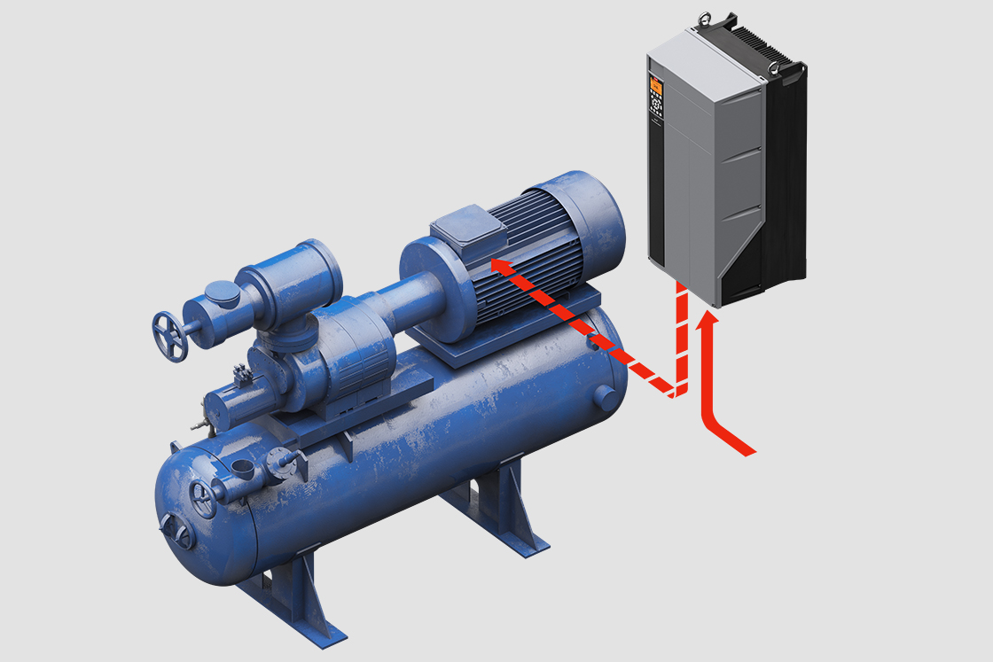
Controlling the VFD:
- Control Methods: VFD can apply various techniques like matter positioners, push buttons, keyparts or foreign control units using sensor feedback.
- Programming: With VFDs often programmable, operators can customize these to specific task requirements through the OI (operator interface).